1. INTRODUCTION
Nanosats have a mass of 1–10 kg and various sizes of 1–12 U. A unit of 1 U represents the size of a nanosat and indicates a cube with an edge length 10 cm. Since 2000, the number of nanosats that have been launched has increased significantly (Nanosats 2020). The limited size of a nanosat reduces its performance in space missions. However, if the missions are carried out with several nanosats in a satellite formation, the performance can be improved. Thus, many space missions use satellite formation flying for acquiring three-dimensional observations, obtaining multiple data observed over time at the same location, space interferometry for stellar and galaxy physics, and collecting space environment data.
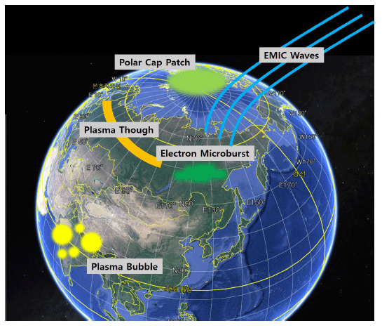
There are several studies on observing the near- Earth space environment using nanosats. The INSPIRE (Interplanetary NanoSpacecraft Pathfinder In Relevant Environment) mission conducted by NASA’s Jet Propulsion Laboratory monitors the effects of solar wind (Klesh et al. 2013). The FIREBIRD (Focused Investigations of Relativistic Electron Burst Intensity, Range, and Dynamics) mission observes electronic microbursts occurring in the magnetic field (Kluper et al. 2009). The SNIPE (Small scale magNetospheric and Ionospheric Plasma Experiments) mission proposed by the Korea Astronomy and Space Science Institute (KASI) will study the near-Earth space environment using four nanosats flying in formation (Fig. 1). The SNIPE nanosats’ mission is to observe the irregular and transient physical phenomena in the ionosphere (Hwang et al. 2018). Moreover, the aim of the SNIPE mission is to analyze the phenomena’s characteristics, and the cause and principle of these occurrences. As these physical phenomena occur very irregularly in near-Earth space, it is important to observe the duration and spatial extent of the phenomenon. Thus, satellite formation flying will be employed by using four nanosats for the SNIPE mission. The main goal and contribution of this study is to design and verify a satellite formation flying scenario for SNIPE.
Studies on multi-satellite formation flying have been conducted in various topics. A study to determine the initial conditions for the formation of multiple satellites has been performed (Yoo & Park. 2011). A relative navigation technique has also been investigated based on GPS measurements (Lee et al. 2015) and laser-based measurement (Lee et al. 2018). Theoretical studies have analyzed the performance of optimal control for reconfiguration of formation flying using a sliding mode technique (Lim et al. 2003), multiple impulse (Kim et al. 2009), state-dependent Riccati equation technique (Park et al. 2011), and generating function (Lee et al. 2013). A software-in-the-loop simulator was developed to validate the algorithms in the intended environment with the integration of attitude and orbit for satellite formation flying (Park et al. 2013). Moreover, an integrated attitude and orbit hardware-in-the-loop simulator was developed for testing a navigation and control algorithm for satellite formation flying (Park et al. 2013). Furthermore, a testbed was implemented to demonstrate multiple satellite operations in proximity (Eun et al. 2018). All of these studies have focused on a fixed size of satellite formation flying. Compared with the previous studies mentioned above, the main contribution of this paper is to design an appropriate satellite formation flying concept that can observe temporal physical phenomena as well as spatial phenomena by changing formation size with respect to time.
In section 2, the requirements of satellite formation flying are explained for the SNIPE mission. In section 3, a cross-shape flying formation is designed and analyzed. In section 4, a square-shape flying formation is designed and analyzed. In section 5, an along/cross-track flying formation is designed and analyzed. An appropriate flying formation is chosen and exhibited in section 6. Section 7 summarizes this study.
2. REQUIREMENTS OF SATELLITE FORMATION FLYING FOR THE SNIPE MISSION
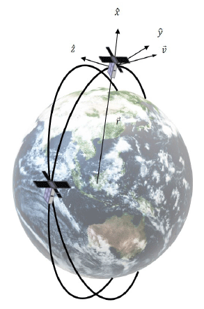
To represent the relative orbits of satellite formation flying, a relative coordinate system to describe the motion of each satellite should be established. The center of the coordinate system is the center of mass of the chief satellite located in the reference orbit that describes the relative orbit of each satellite. This coordinate system is called the LVLH (Local Vertical Local Horizon) coordinate system (Fig. 2). The x-axis is called the radial direction, the y-axis is called the along-track direction, and the z-axis is called the crosstrack direction. The mission needs to observe a small-scale physical phenomena in the geomagnetic field so four nanosats perform the formation flying. In addition, the size of the formation should be changed during the mission lifetime to obtain data at different scales. The requirements of formation flying for the SNIPE mission are as follows. The distances between four nanosats must increase from 10 km to more than 100 km in the along-track and cross-track directions at the equator and latitude 70° during the mission lifetime of six months. In addition, formation maintenance is required to align the four nanosats in the along-track or cross-track direction within 10°. Moreover, formation reconfiguration is also required to increase the inter-satellite distance to meet formation flying requirements. The accumulated ΔV required for formation maintenance and reconfiguration should be less than 20 m/s for each nanosat. The thrust required for each nanosat can also be equalized. This study proposes three formation maintenance and reconfiguration scenarios: a cross-shape (+) formation, a square-shape (□) formation, and an along/cross-track (ㅣ━) formation. After analysis of their characteristics, an appropriate formation flying design is chosen for the SNIPE mission. The crossshape (+) formation consists of a cross shaped with four nanosats, gradually increasing the cross distance between nanosats. The square-shape (□) formation gradually departs from the reference orbit in a diagonal direction. The along/ cross-track (ㅣ━) formation flying is aligned in an alongtrack direction first and a cross-track direction later with respect to the reference orbit, and gradually recedes in the cross-track direction. The orbit simulation contains gravity model JGM-3 70 by 70, air drag, solar radiational pressure, and the gravity of the Moon and Sun. All the details on the spacecraft formation design for the SNIPE mission can be found in the reference (Kang 2018).
3. CROSS-SHAPE (+) FORMATION FLYING
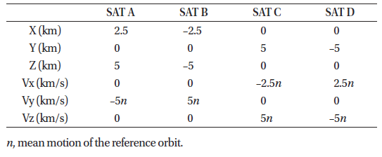
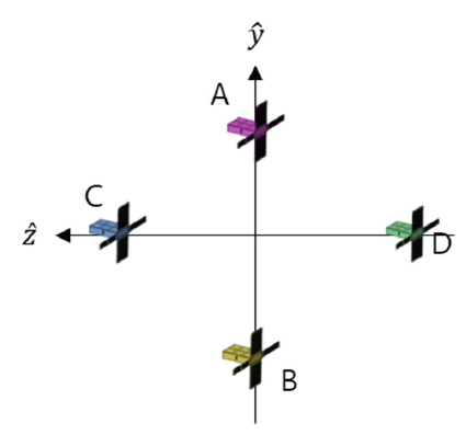
The cross-shape (+) formation scenario is that four nanosats (Nanosats A, B, C, and D) form a cross shape and maintain the shape of the formation near the equator and the North Pole. When the reference orbit is above the equator, Nanosat A is located in the positive along-track direction and Nanosat B is located in the negative alongtrack direction. Subsequently, Nanosat C is located in the positive cross-track direction of the reference orbit and Nanosat D is located in the negative cross-track direction. Each nanosat performs a projected circular orbit (PCO) motion with respect to the reference orbit. PCO means that the relative orbit on the along-track and cross-track plane is circular. Each nanosat is controlled to increase the PCO radius constantly over time from 10 km to more than 100 km. Fig. 3 shows the initial relative orbits of the four nanosats in the cross-shape flying formation. Table 1 shows the initial relative orbit of the cross-shape formation flying with respect to the reference orbit, with orbital elements such as a semi-major axis of 6,978 km, eccentricity of 0.00001, inclination of 97.8°, right ascension of ascending node (RAAN) of 187.3°, argument of perigee of 0°, and true anomaly of 0°. n is the mean motion of the reference orbit.
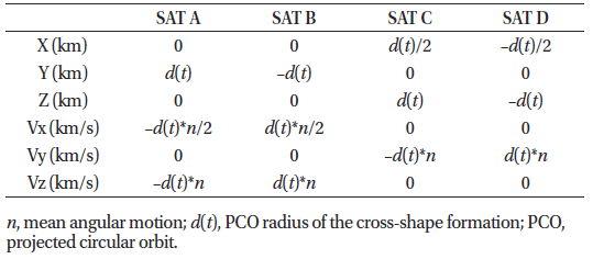
We check the relative orbit of each nanosat above the equator at every cycle and control it if the position of the nanosat is out of the specified criteria due to orbital perturbations. The criteria for performing the relative orbit control are as follows. When the angle between the initial position vector given in Table 1 and the current position vector is more than 10° on the yz-plane from the reference orbit, two impulses (ΔV1, ΔV2) are applied to acquire the required relative position and velocity. The first thrust (ΔV1) makes the nanosat reach the desired position, and the second (ΔV2) can match the velocity of the nanosat with the desired velocity according to the desired position. The relative Lambert’s problem is used to determine the interval between the two thrusts and the required velocity increment, ΔV1, to reach the desired position (Wen et al. 2014). When the nanosat arrives at the desired position by ΔV1, a second velocity increment (ΔV2) can be applied to allow the nanosat to follow a PCO motion with respect to the reference orbit. When the first impulse thrust (ΔV1) is applied at the position of the nanosat above the equator, there is a gap of Δθ up to the second impulse thrust (ΔV2) from the first impulse thrust (ΔV1). The magnitudes of ΔV1 and ΔV2 can be calculated and depend on Δθ (Wen et al. 2014). In this study, it is analyzed that the required total thrust ΔV ( = ΔV1 + ΔV2) has the smallest value near Δθ ~270°. Thus, the phase difference between the two thrusts is set to 270° in this study. Table 2 shows the desired position and velocity of the nanosat to reach through the relative orbit control over the equator. The d(t) in Table 2 is the PCO radius of the cross-shape formation and varies with respect to the elapsed time. The first thrust, ΔV1, can be calculated to reach the position after orbital period (Δθ ~270°) from the initial position and velocity. The second thrust, ΔV2, can also be calculated to reach the desired velocity in Table 2 after 3 4 π orbital period (Δθ ~270°).
For the cross-shape formation flying, relative orbit controls are performed using Table 2 to keep the shape of the formation and to increase its size. The cross-shape (+) formation is numerically simulated for six months, and the time taken for the PCO diameter of each nanosat to reach 100 km is calculated. It takes 173 days, 177 days, 179 days, and 180 days for Nanosats A, B, C, and D, respectively. In Fig. 4, the accumulated thrust required for each nanosat during the mission lifetime is shown. Nanosats A and B required an accumulated thrust of about 250 m/s for six months, whereas Nanosats C and D required an accumulated thrust close to 800 m/s. The magnitude of the thrust at each moment was calculated based on the Lambert’s problem, and the orbit control was performed whenever the angle criterion was exceeded. Although the relative orbit control is performed under the same conditions, the difference in total accumulated thrust of Nanosats A and B and Nanosats C and D is due to the differences in the initial orbital conditions. The most dominant perturbation at 500 km altitude is the J2 orbital perturbation. The J2 perturbation changes the RAAN value of a satellite in orbit, and the degree of change is determined by the semi-major axis, eccentricity, and inclination of the satellite, of which the influence of the inclination is most dominant. The difference between the reference orbit and Nanosats C and D is larger than that of Nanosats A and B, and thus their RAAN values are varied significantly. Therefore, continuous RAAN control is required to maintain the PCO size of Nanosats C and D. Because the thrust required for inclination and RAAN control in the orbital element is larger than that of other orbital elements, the accumulated thrust of Nanosats C and D is very large.

4. SQUARE-SHAPE (□) FORMATION FLYING
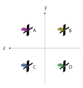
The second formation flying scenario is that in which the four nanosats (Nanosats A, B, C, and D) form a squareshape (□) formation and maintain it at the equator and latitude 70°. When the reference orbit is above the equator, Nanosats A and B are located in the positive along-track direction and Nanosats C and D are located in the negative along-track direction. At the same time, Nanosats A and C are located in the positive cross-track direction and Nanosats B and D are located in the negative cross-track direction. Nanosats A and B, and Nanosats C and D, which are arranged in a line in the cross-track direction with respect to the reference orbit, are paired (shown in Fig. 5). The two nanosats pairs then cross each other in the crosstrack direction. The four nanosats perform a formation reconfiguration so that they gradually move away from the reference orbit diagonally.
For the square-shape (□) formation flying, relative orbit controls are performed once a day to maintain the shape of the formation and to increase its size. At this time, the relative orbit controls are divided into two steps: the along-track direction control and the cross-track direction control. Each control is performed alternately every other day. The control period is determined based on the concept of operations. To overcome the limited thrust of the nanosat, the use of orbital perturbations is suggested as a strategy to increase the relative distance between satellites. The most dominant orbital perturbation at an altitude of 500 km is the J2 perturbation. Therefore, the J2 terms are used, which secularly change over time in the Lagrange planetary equation (LPE) (Vallado 2013). The magnitude of ΔV was determined to change the inclination corresponding to the relative distance.
As the initial relative orbit of the nanosat is calculated by the linearized solution of the HCW (Hill–Clohessy- Wiltshire) equations (Clohessy et al. 1960) in the relative orbital motion equation, the relative distance is diverted due to the linearization error during the long-term mission.
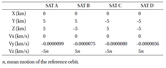
Especially due to orbital perturbations, nanosats drift in the along-track direction with respect to the reference orbit. The initial y-axis velocity values in Table 3 are set to maintain the formation because each nanosat is moved away in the along-track direction from the reference orbit due to linearization errors and perturbations. Secularly moving away from the reference orbit in the along-track direction causes a difference in the mean motion of each nanosat. Assuming a two-body motion, the mean motion of the satellite is determined independently through the semi-major axis. However, considering the perturbations, other classical orbital elements may affect the mean motion. The perturbations of the zonal harmonics due to the non-spherical gravitational field do not significantly affect the semi-major axis, but cause changes in RAAN (Ω), argument of perigee (ω), and initial mean anomaly (M0). Therefore, the new mean motion should be considered according to the effects of perturbations. The y-axis velocity values of the initial relative orbit in Table 3 are calculated by matching the reference orbit’s new mean motion (neff) with the new mean motion of the four nanosats.
The formation maintenance of the four nanosats is carried out through position control in the along-track direction. As the control criteria, each nanosat must remain within 10° of the relative position for the square-shape (□) formation configuration near the equator. The desired orbit of the nanosat restrained in the along-track direction can be defined as a function of time. In addition, the y-axis velocity () required to track the desired orbit of the nanosat can be found. The control of the along-track direction is performed every two days on the equator, so that the required velocity value can be obtained. However, the actual required thrust iΔV is not the value of (). By analyzing the HCW equations, it can be recognized that the y-axis position of the relative orbit is proportional by a factor of –3 to the initial y-axis velocity. Therefore, the thrust ΔV required for the along-track direction control should be .
The cross-track direction control of each nanosat is performed as follows. In the LVLH frame, the cross-track direction corresponds to the normal vector direction of the orbital plane of the satellite in the inertial system and is related to the orbital inclination and RAAN. A distance increment in the cross-track direction between the satellites implies an increment in the difference between the satellites’ RAAN, and an increment in the difference in the orbital inclination near the pole. It is known that the orbital inclination is constant, whereas the RAAN is constantly changed by the influences of zonal harmonics in orbital perturbations (Vallado 2013). Hence, only the maneuvering of orbital inclination is performed, and consequently, the difference in RAAN between the nanosats is naturally increased by the zonal perturbations. To control the positions of the four nanosats in the cross-track direction in the vicinity of the North Pole, the orbital inclination must be changed by about 0.125°. Each nanosat controls the orbital inclination and the along-track direction for formation maintenance during the mission lifetime.
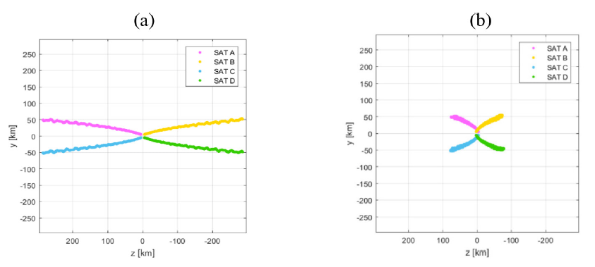
The square-shape (□) formation is also numerically simulated for six months. After six months, the positions on the LVLH coordinate system of the four nanosats at the equator and latitude 70° are separated by 100 km. Fig. 6 shows the position changes of each nanosat on the yz plane at the equator and latitude 70° over six months. The accumulated thrust required for each nanosat in the square-shape formation is about 16.6 m/s. In addition, the fuel distribution is satisfied so that the same results can be generated by the 0.01 m/s thrust level required for each nanosat. In the simulations, the relative orbit control for formation maintenance is performed well, so that the relative position is maintained within 10° of the four nanosats.
5. ALONG/CROSS-TRACK (ㅣ━) FORMATION FLYING
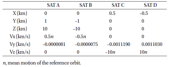
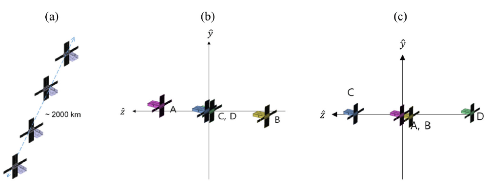
After departure from a launch vehicle, the distances between the four nanosats will be continuously increased in the along-track direction due to orbital perturbations and initial velocities. After one month, orbital maneuvers will be performed to reduce the distances between the four nanosats. The distance will then be continuously decreased for two months. This is called along-track formation flying. When the along-track formation is terminated, orbital maneuvers will be performed to make the initial orbital conditions for cross-track formation flying (Fig. 7(a)). These maneuvers for along-track formation flying cost about 0.2 m/s in velocity changes. The four nanosats (Nanosats A, B, C, and D) then form an along-track (ㅣ) formation for two months, before changing their orientation to form a cross-track (━) formation for three months. During the along-track formation, the nanosats will observe temporal differences in the near-Earth space environment, and they will then observe spatial differences during cross-track formation. In this study, a cross-track formation scenario is designed and the initial relative orbits of the four nanosats are set as follows. When the four nanosats pass over the equator, Nanosat A is located in the positive cross-track direction of the reference orbit, and Nanosat B is located in the negative cross-track direction of the reference orbit. Nanosats C and D are located at the same reference orbit when they pass over the equator (Fig. 7(b)). In contrast, when the nanosats pass the North Pole (Fig. 7(c)), Nanosat C is located in the positive cross-track direction and Nanosat D is located in the negative cross-track direction. Nanosats A and B are located at the same reference orbit when they pass over the North Pole. The initial orbit of the nanosats can be divided into classical orbital elements to distinguish the characteristics of the initial orbit. Nanosats A and B have the same inclination as the reference orbit, but different RAAN. By setting the initial orbit in this way, it is possible to maintain proper spacing between the four nanosats at latitude 70°, where most physical phenomena are observed. Table 4 shows the initial conditions of the cross-track formation flying in LVLH coordinates with respect to the reference orbit, and Table 5 represents the initial classical orbital elements of the reference and nanosats. Two nanosats have different RAAN and the other two have different inclination.

|
The formation maintenance and reconfiguration of the cross-track formation is similar to that of the square-shape formation flying scenario. The change in the total inclination of the four nanosats can be calculated based on the fact that the relative distance between the nanosats reaches 100 km after three months above latitude 70°. The minimum inclination to be controlled is calculated to be 0.12° over the three months by using the HCW equation and LPE. In the first 1.5 months, the inclination is controlled by 0.00183° per day, and in the latter 1.5 months, it is controlled by 0.000833° per day. Nanosats A and C are controlled in the negative direction of inclination angle, and Nanosats B and D are controlled in the positive direction of inclination. The positional component of the along-track direction should be kept the same as the initial position of the reference orbit to maintain a cross-track formation. Hence, when controlling the orbit inclination once a day because of the limitation in communication with nanosats, the thrust for maintaining the position in the along-track direction should also be applied simultaneously. The magnitude of ΔV was determined to alter the inclination and RAAN corresponding to the relative distance at the North Pole and equator, respectively.
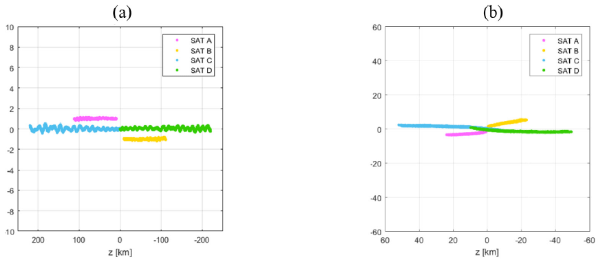
Fig. 8 presents the position of each nanosat at the equator and latitude 70° for three months. The cross-track formation flying scenario requires increasing the relative distance between the nanosats to 100 km over three months. The accumulated thrust required for each nanosat in the crosstrack formation is about 15.6 m/s. This formation scenario meets the thrust limit, and the initial trajectories of the four nanosats are set appropriately, so that the thrust required for each nanosat can be equalized. In addition, the relative orbit control for formation maintenance is well performed in the simulation, and it is also confirmed that the relative position is maintained within 10°.
6. APPROPRIATE FORMATION FLYING FOR THE SNIPE MISSION
Of the three concepts of formation flying suggested in sections 3, 4, and 5, we should choose the most appropriate concept that satisfies the requirements described in section 2. For all three flying formations, the positions of the four nanosats on the LVLH coordinate system at the equator and latitude 70° are continuously separated from 10 km to over 100 km for the mission lifetime. Table 6 shows the accumulated ΔV of each concept. Only the square-shape (□) and the along/cross-track (ㅣ━) formation flying satisfy the thrust limit condition of 20 m/s, whereas the cross-shape (+) formation does not. If along/cross-track formation flying is utilized, the four nanosats will observe temporal differences in the near-Earth space environment during along-track formation, and will then observe spatial differences during cross-track formation. When other flying formations are used, two nanosats can be used to observe the temporal and the other two nanosats can be operated to observe the spatial differences. The along/cross-track formation is chosen for the SNIPE mission because it can extend the observation area of the physical phenomenon by utilizing all four nanosats.

|
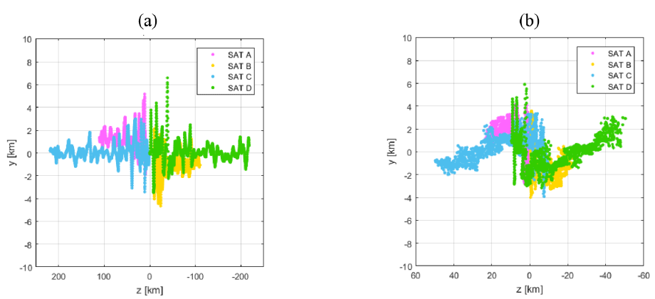
Three different thrust errors are applied to the crosstrack formation scenario to obtain more realistic thrust profiles over three months. The first thrust error is the thrust position error due to the orbit determination error. The thrust position error is set to 50 m. The second thrust error is the thrust direction error due to the attitude determination and control error. The thrust direction error is set to 2°. The third thrust error is the thrust magnitude error caused by thruster performance. The thrust magnitude error is set to 10%. Simulations are carried out including the three thrust errors. In the GMAT (General Mission Analysis Tool) simulations (NASA GSFC 2017), the errors can be applied using the random function in the process of calculating the thrust vector. Fig. 9 shows the changes in position of the four nanosats over the equator and latitude 70° over three months. The results of the cross-track formation simulations including the thrust error also satisfy the formation flying requirements, but the change in the along-track direction position is increased. The reason for this is that the relatively large cross-track direction thrust influences the change of the thrust magnitude in the alongtrack direction due to the influence of the thrust error. It is confirmed that the cross-track formation flying simulation satisfies the formation flying requirements. Table 7 shows that the accumulative ΔV of the four nanosats is less than 20 m/s and the difference in the accumulative ΔV between the nanosats is about 2 m/s. Therefore, the cross-track formation flying scenario using the thrust error satisfies all of the design conditions.

|
7. CONCLUSIONS
In this paper, three satellite formation flying concepts to observe the near-Earth space environment as part of the SNIPE mission are analyzed. For the cross-shape formation scenario, four nanosats form a cruciform formation with respect to a reference orbit. For the square-shape formation scenario, four nanosats form a rectangular formation with respect to a reference orbit. For the along/cross-track formation scenario, four nanosats constitute a formation that is aligned in a vertical direction with respect to the reference orbit’s progressing direction. The along/cross-track formation flying is selected as a scenario that meets the design requirements and better matches the scientific objectives of the SNIPE mission. The formation flying scenario satisfies the formation flying requirements and the accumulative ΔV is less than 20 m/s. In addition, it can be confirmed that all design conditions are satisfied because the difference in the accumulative ΔV of each nanosat is within a maximum of 2 m/s. In scientific terms, the four nanosats observe the temporal and spatial differences in physical phenomena, which is advantageous in that the observation resolution can be enhanced. The proposed method for maintaining and reconfiguring a formation of more than 100 km with limited performance of thrusters is to control their relative orbits using various perturbations present in outer space. The results of this study show that the initial relative orbit and relative orbit control scenario for formation maintenance and reconfiguration satisfy both the formation flying requirements set on the basis of science missions in the SNIPE mission, and formation flying requirements and thrust constraints. If the final scenario presented in this study is applied to the SNIPE mission, it will be possible to observe temporal differences during the along-track formation and spatial differences during the cross-track formation for irregular and transient physical phenomena occurring in the ionosphere.
