1 INTRODUCTION
Space situational awareness (SSA) has become a major concern of both military and commercial significance owing to the increase in space objects, including active satellites and space debris. An important aspect of SSA is space surveillance and tracking (SST), that is, the ability to detect and predict the orbit of space objects around the Earth. The most comprehensive data related to objects in space are obtained from the United States Space Surveillance Network (SSN) that comprises a sensor network consisting of several optical and radar sensors. According to the box scores of the Satellite Situation Report issued on November 22, 2018, the number of unclassified space objects in the catalog of the U.S. SSN was 43,717. Of these, only 19,256 remain in orbit (Space-Track 2018). These cataloged space objects are typically larger than 10 cm in a low Earth orbit (LEO, below 2,000 km altitude), and larger than 1 m in a geostationary orbit (GEO, at altitudes close to 25,786 km) (Klinkrad et al. 2007;Eilers et al. 2016). The minimum size for cataloged space objects is limited by sensor sensitivity, which is reduced by 1/16 when doubling the target distance to a radar and by 1/4 when doubling the target distance to a telescope (Klinkrad et al. 2007;Halte 2012). This is the main reason why a radar system is primarily used for LEOs, and an optical system for GEOs.
The SSA system including optical and radar systems needs to be used considering the advantages and disadvantages of each of these two types of systems to obtain maximum detection performance. The main requirement of the SSA optical and radar systems is the capability to detect and track space objects and several studies have investigated the overall performance and complexity, technological readiness, and development risks associated with these systems (Ono et al. 2001;Halte 2012;Eilers et al. 2016;Choi et al. 2017b).
In Korea, to address the requirements of SSA, a space situational awareness program that includes efforts to develop an SST system and an integrated analysis system is underway (Choi et al. 2015a, b, 2017a). An optical wide-field patrol network (OWL-NET) completed in 2016, with five optical telescopes in five countries around the world, is currently in the calibration and verification phase (Choi et al. 2017b;Lee et al. 2017;Park et al. 2018). However, the limitations of the optical system make its use alone inadequate for SSA activities (Park et al. 2013;Park et al. 2015;Bae et al. 2016;Choi et al. 2016;Park et al. 2016;Choi et al. 2017b). Therefore, the development of a radar system for SSA has been considered and a preliminary study conducted for analyzing the performance of radar systems detecting and tracking space objects in LEOs. Lee et al. (2018) proposed a radar technology for the detection and tracking of space objects using an L-band phased array radar system and confirmed the possibility for using it independently for building SSA capability.
A radar system is well suited to observe space objects compared to an optical system because of the former's all-weather and day-and-night performance. However, a radar system has a relatively short detection range and requires massive development costs. To perform the surveillance of space objects in a LEO, the most suitable options have to be considered, such as achievable radar cross-section (RCS), required operating power, technical readiness level (TRL) of the components, and costs. Previous studies (Lee et al. 2018;Moon et al. 2018) have shown that L-band phased array radar has been selected to satisfy the required mission for national SSA. Consequently, to reduce the development costs, the requirements of the radar system for SSA necessitates the use of digital processing techniques.
Radar signal processing techniques can be used to improve the signal-to-noise ratio (SNR); for instance, pulse integration can be employed as a method to maximize detection range and minimize development costs (Skolnik 2001). Pulse integration is a signal processing technique that transmits and receives a signal to increase the SNR. To obtain this effect, the reflection signal of a target for each pulse has to exist in the same range cell. However, the space objects in a LEO travel at speeds of 7–8 km/s faster than the faster guided missiles detected using a conventional radar system. Thus, in the case of space objects, since range cell migration occurs where the target reflection signal from each transmitted and received pulse for pulse integration exists in different range cells, and the desired effect of increased SNR cannot be obtained simply through integration. To improve the radar detection performance regarding high-speed targets, several signal processing methods such as Hough transform, Radon transform, and keystone transform have been studied (Carlson et al. 1994;Xu et al. 2011;Mukhopadhyav & Chaudhuri 2015;Huang et al. 2018). These methods compensate for the range cell migration phenomenon for high-speed targets and improve the SNR through pulse integration. In the conventional pulse integration method, no additional gains due to the range migration phenomenon occurs.
In this study, we investigate the performance of the radar system that detects space objects using a target detection method based on the Hough transform. This transform is used to detect target tracks in a multidimensional data space filled with return data from the radar (Carlson et al. 1994).
This paper describes the Hough transform algorithm and the reflection signal modeling for space objects. The improvement of the SNR in the Hough transform method is compared to that in the conventional pulse integration method without range compensation and the effect on the SSA radar system specification is described.
2 SIGNAL MODELING
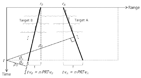
When pulse integration is carried out with the aim of improving the SNR for radar target detection, the range cell migration phenomenon occurs where the target signal moves with time, as shown in Fig. 1, if the target travels at a high speed. Hence, for the case in which target A travels away from the radar and target B approaches the radar at high speeds, the horizontal axis represents the range cell of the received signal for a single pulse and the vertical axis represents the time for each repetitively received pulse during pulse integration. That interval is the pulse repetition time (PRT). That is, when the same pulse is transmitted and received several times to a high-speed target for pulse integration, the range cell of the target signal for each pulse is not the same. Therefore, if pulse integration is carried out as it is, the target signals of different range cells are not integrated and the signal processing gain according to the pulse integration cannot be obtained.
The Hough transform takes range and time and transforms them into the length ρ and angle θ domain, as shown in Fig. 1. As a result, length ρ is related to range r and angle θ to speed v of the target, respectively. The relationship with time t is expressed as
where PRT refers to the pulse repetition time and n refers to the n-th pulse.
Applying Eq. (1) to the radar data matrix, the Hough transform can be expressed as(2)
where Data(n,r) is the radar data matrix, which is the signal amplitude at range r for the n-th pulse, and N is the total number of pulses composing the radar data. If all the pulses exist in the same range cell after pulse integration owing to a slow target speed, the value of θ becomes 0 and the transform can be expressed as follows.(3)
It can be confirmed that this is the same as the conventional pulse integration formula.
In case of space objects traveling at high speeds, application of the conventional pulse integration method degrades the detection performance owing to the range cell migration phenomenon. Therefore, radar reflection signal modeling for space objects traveling at high speeds is necessary to simulate the corresponding performance.
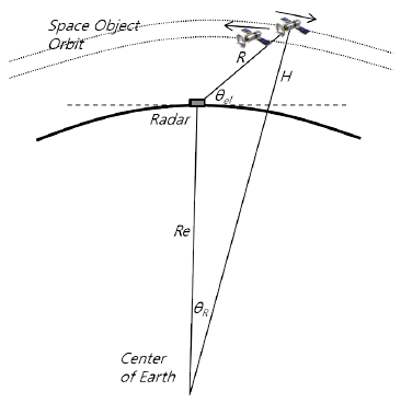
Fig. 2 shows the geometric relationship between the SSA radar and a space object for the case where the space object is traveling over the radar. H is the altitude of the space object and θel is the elevation angle between the radar and the space object. Here, Earth was modeled as a sphere with a radius of Re. In this case, the range between the radar and the target can be calculated using the following quadratic equation.
Using Eq. (4), the signal amplitude Pr and the noise amplitude Pn of the signal reflected off the target and received by the radar can be calculated as follows:(5)(6)
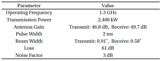
where Pt is the radar transmission power, Gt and Gr are the transmit antenna gain and receive antenna gain, respectively, σ is the RCS, λ is the wavelength, R is the range between the radar and the space object, k is Boltzmann’s constant, T is the temperature, L is the signal loss, B is the bandwidth, and Fn is the noise factor. These values were used in the design specifications of the L-band phased array radar for the SSA radar system. Lee et al. (2018) designed the upward-oriented phased array radar to be able to detect a space object with an RCS of 0.0078 m2 at a range of 1,567 km. The detection criteria was based on a single pulse, the probability of detection was 80 %, and the false alarm probability was 10-6. Table 1 shows the design parameters for the SSA radar system (Lee et al. 2018).
For the radar transmitting signal modeling, the generally widely used linear frequency modulation (LFM) waveform was applied as follows (Xu et al. 2011):(7)
where Tp is the radar pulse width, that is, the pulse repetition period, τ is the time of the radar pulse starting point, and γ is the frequency rate of the LFM signal. The modeling for the signal reflected from a single target and multiple pulse transmission/reception are expressed as follows:(8)(9)
where Ar is the magnitude of signal voltage, c is the speed of light, and n is the number of transmission pulses ranging from 1 to N.
3 SIMULATION RESULTS
To verify the difference between the pulse integration method with no range compensation and the Hough transform, a simulation signal was generated and signal processing simulation was carried out for comparison. The simulated signal was used for the reflection signal generation model for the space object target described in Section 2. Table 2 shows the model parameters.
The scenario assumes that the two space objects are at altitudes of 1,200 km and 1,190 km respectively and are located at an elevation of 45°. In these cases, their ranges are 1,580 km and 1,567 km. The velocity of the space object assumed a target moving to the right at 7 km/s and a target moving to the left at 7.5 km/s. The target sizes are assumed to be 10 cm and 3 cm in diameter space objects, and the RCS values, a radar reflection coefficient, are 0.0078 m2 and 0.000707 m2, respectively. The 10 cm space object could be detected with a single pulse but the 3 cm space object was detectable after improving the SNR through the Hough transform. The pulse integration number for the Hough transform was set to 32.
-
1) Single Pulse Detection Results (10 cm spherical object)
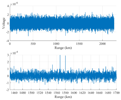
Fig. 3 shows the target signal formed with only pulse compression for a 10 cm spherical object. While the target signal was indiscernible as it was not visible due to the noise before the pulse compression (up), the target signal was observable at 1,580.3 km and 1,567.8 km after pulse compression (down), and target detection was possible.
-
2) Problems with Pulse Integration without Range Compensation
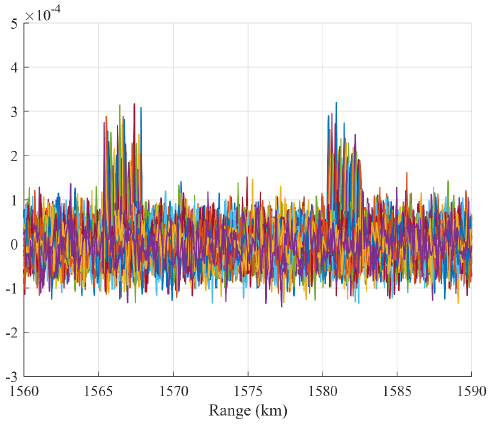
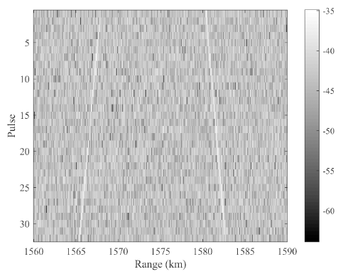
Fig. 4 shows the multiple pulse signals reflected off the 10 cm spherical target in the range-time domain. The white lines represent the reflected signals from the targets and it can be seen that the range cell moves with time. For the first pulse, targets A and B were at 1,580 km and 1,567.8 km, respectively, and for the 32nd target signal, it can be observed that the range of target A increased while that of target B decreased. When the pulses are integrated without range compensation, the results shown in Fig. 5 are obtained. Since the signal peak of each pulse varies, not only is the SNR improvement from the integration not possible, but the signal peak is spread out, and therefore accurate detection is not possible.
-
3) Hough Transform Application for Range Cell Migration Compensation
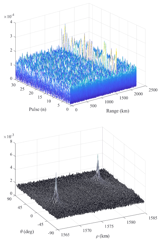
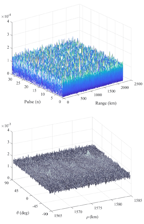
To overcome the range cell migration phenomenon, the Hough transform method was applied. The simulation results are shown for the 10 cm spherical target that can be detected with only a single pulse and the 3 cm target that cannot be detected with a single pulse. Fig. 6 shows the multiple pulse data for the 10 cm spherical target (up) and the Hough transform data (down). In the multiple pulse data, it can be observed that the target signal is formed even for a single pulse while a very strong peak is formed in the Hough transform. The simulation results for the 3 cm spherical target, which cannot be detected with a single pulse, are shown in Fig. 7. While the signal is completely indiscernible in the pulse range data (up), the peak formation can be observed in the Hough transform. It can be seen that the noise component is larger than that in Fig. 6.
The Hough transform carries out signal integration with compensation for range deviation due to the range cell migration phenomenon, and thus an SNR improvement equivalent to that of noncoherent integration can be expected. The performance of noncoherent integration varies according to the detection probability (Pd), false alarm probability (Pfa), and Swerling model. Although the lower bound of the performance is , this is a very conservative value, and according to the literature, the performance enhancement of noncoherent integration for Pd = 0.9 and Pfa = 1.e-6 is as shown in Fig. 8 (Richards 2014).
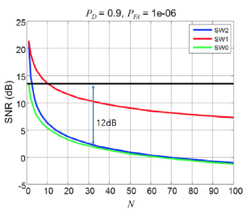
Since small space objects have dimensions smaller than the wavelength, such objects are close to point targets and the RCS fluctuation model can be modeled with Swerling 1 to 0. When N is 32, a signal processing gain of 12 dB can be obtained. This gain can reduce the transmission and reception antenna areas to approximately 40 % as well as significantly reduce radar costs. Taking this into considerations, the L-band phased array radar system design for SSA of Lee et al. (2018) can be summarized as Table 3.

|
4 CONCLUSION
In this study, the characteristics of space objects, which are the targets of SSA, and the radar system were analyzed, and the method for improving SNR of target signal was proposed. Considering the range migration phenomenon that occurs during the detection of space objects, it was shown that the SNR could not be improved simply by using the pulse integration method. The Hough transform, which is a method of compensating for range migration, was applied to the problem of space object detection for a SSA radar system. Simulation results showed that the application of the transform resulted in target formation in cases where the signal was almost indiscernible and in the presence of noise for a single pulse.
The correlation between the number of pulses and the gain in the SNR was described. The method of improving the SNR in a range migration environment where the range cell moves with time was presented. In the simulation, the Hough transform integrating 32 pulses resulted in a signal processing gain of approximately 12 dB. In other words, applying the signal processing method using the Hough transform can reduce the transmit–receive antenna gain of the SSA radar system up to 40 % for the same detection range. Thus, these results show that the size and cost of the SSA radar system can be effectively designed and improved. Accordingly, this gain can be used to improve the target detection performance of a SSA radar system or to reduce of the cost of further SSA radar system development. Furthermore, the improved detection performance of the signal processing gains can be used as a basis for a more comprehensive design of the SSA radar system.
