1. INTRODUCTION
The development of CubeSats has reduced the size of satellites to tens of centimeters, thereby reducing their development and launch costs. For this reason, CubeSat missions have been on a rapidly upward trend. That is, the usage of CubeSats for scientific or technical objectives has increased recently. There have been many CubeSat missions conducted around the Earth for observational purposes or to demonstrate new space technologies at low cost. Also, the lower cost makes it possible for university students to develop experimental satellites by themselves. In line with this international trend, proposals for the development of CubeSats in Korea are also increasing (Han et al. 2015). As lunar science has come to the fore, interest in the exploration of the Moon through CubeSats is significantly growing. The CubeSat can be used to carry out missions of lunar exploration or to realize space technology in deep space environments, while larger satellites have a few limitations (Lakin & Brandon 2011;Johnson et al. 2015).
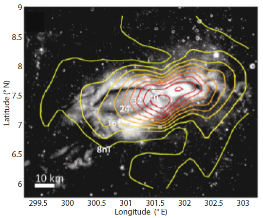
The lunar local magnetic anomaly is one of the emerging study areas in lunar exploration. Studies of the structure of the local magnetic fields help to understand the origin of the lunar local magnetic field and the internal structure of the Moon. In 1959, the Soviet lunar probe, Luna-1, measured the magnetic field of the Moon and determined that the magnetic field was not distributed globally as on Earth (Garrick-Bethell et al. 2013). Later, as Apollo missions discovered rocks magnetized from the lunar surface, they found that the lunar magnetic field was distributed locally on the surface (Pearce et al. 1972;Collinson et al. 1973). Lunar swirl areas with high albedo on the lunar surface, in particular, exhibit high magnetic field strength (Blewett et al. 2011). Therefore, the precedent lunar magnetic investigation, the Lunar Prospector mission, gathered magnetic data above the Reiner Gamma swirl, shown in Fig. 1. However, the Lunar Prospector measured the magnetic field above the swirl at altitudes of over 18 km and could not describe the near-surface magnetic field (Hood et al. 2001). For further understanding of the local magnetic field on the Moon, magnetic field measurements at altitudes of 18 km or less are required, but there is no mission, as of yet, to gather these measurements. Using a small CubeSat, it is possible to analyze the lunar local magnetic field near the surface. When a CubeSat equipped with a magnetometer falls on the Reiner Gamma surface, it will be able to measure the magnetic field in the area and study the magnetic field near the surface (Garrick-Bethell et al. 2013). To measure the lunar local magnetic field over the Reiner Gamma surface, three possible mission orbits are designed in the current study, according to the impacting trajectories over the area. For each orbit scenario, its strengths and weaknesses can be compared by comparing parameters such as ΔV, magnetic field measurement time, and final position error, which are directly related to the success of the mission. From this comparison, an optimal orbit scenario can be selected. In addition, through error propagation analysis of the CubeSat, the probability of mission success can be evaluated in advance.
2. MISSION OVERVIEW
The primary objective of the Lunar Impactor CubeSat mission is to measure the magnetic field near the lunar surface at the Reiner Gamma swirl. This makes it possible to study the formation of the lunar swirl. Furthermore, the study of the proton reflection phenomenon of the lunar surface and the electric field of the swirl surface can be conducted through additional solar wind measurements.
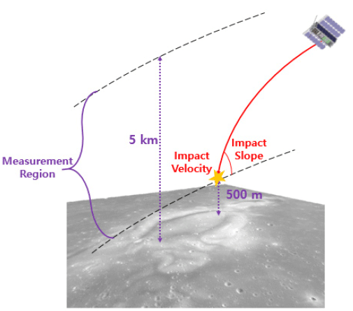
Ian Garrick-Bethell at the University of California, Santa Cruz has proposed a mission concept to solve this difficulty of near-surface observation (Garrick-Bethell et al. 2013). Fig. 2 shows the concept using a 3U CubeSat to measure the lunar magnetic anomaly near the Reiner Gamma swirl by impacting the lunar surface. The CubeSat is released from its mothership’s lunar orbit and descends to the Reiner Gamma swirl. While descending toward the lunar surface, it can measure the near-surface magnetic properties. This makes it possible to collect magnetic data below the altitude of 18 km and get a better understanding of the lunar magnetic anomaly than what previous missions have revealed.
To accomplish this mission objective, the mission require-ments should be defined as follows. The center of the Reiner Gamma swirl, which is the target impacting point, is located at the selenographic coordinates of 7.5° north latitude and 59° longitude, and the radius of the swirl is as large as 32.76 km. The CubeSat is designed to impact within the swirl region at a specified time, particularly at noon. Before impacting, it is assumed to follow a polar orbit. The magnetic measurements will be conducted from when it reaches an altitude of 5 km to when it impacts the surface, so that it can collect the near-surface magnetic data. The slope of the impacting trajectory affects not only the measurement time but also the measurable region. For the desired measurement, the slope is required to be between 10° and 20°. The velocity of the impacting CubeSat also affects the measurement time, in which a longer time is preferred. The accuracy of position determination of the CubeSat is assumed to be 1 km.
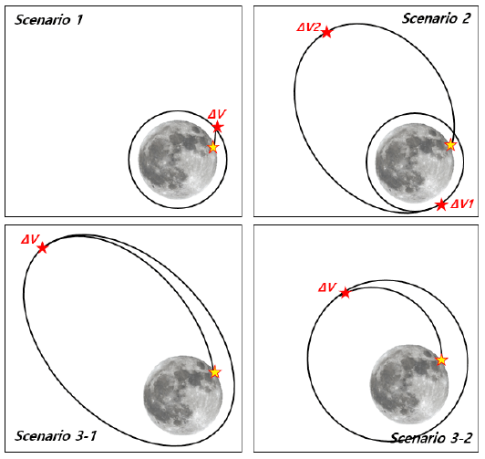
Three kinds of operational scenarios are designed in Fig. 3. Scenario 1 is for the CubeSat to be released from some point on a circular orbit at 100 km altitude. Then, the CubeSat falls to the lunar surface. Scenario 1 is the basic impacting scenario and requires only one maneuver, as shown in top left of Fig. 3. In scenario 2, shown in top right of Fig. 3, the orbiter will first release the CubeSat from a circular orbit at 100 km altitude just like scenario 1. However, after the first release, the CubeSat travels far along the transfer orbit. When the CubeSat reaches the apoapsis of the elliptical orbit, the second maneuver is conducted. After the second maneuver, the CubeSat falls to the lunar surface. The release at the higher altitude might offer an advantage of a smaller required impulse. However, the idea of traveling far away from the initial orbit appears to have many operational risks. Scenarios 3 is an alternative plan to compensate for those risks. In scenario 3-1 and 3-2, the lunar orbiter releases the CubeSat in the lunar orbit insertion (LOI) stage (Choi et al. 2014). That is, the CubeSat is released at the apoapsis of the first and second LOI orbit. The LOI orbit is larger than the circular orbit of 100 km altitude and offers an advantage of a smaller impulse, as the CubeSat does not have to intentionally travel far away. For scenario 3-1, shown in bottom left of Fig. 3, the given LOI orbit is the elliptical orbit at 100 km altitude at periapsis and a 12 hr orbital period. In the case of scenario 3-2 shown in bottom right of Fig. 3, the given LOI orbit is the elliptical orbit at 100 km altitude at periapsis and a 3.5 hr orbital period. Scenarios 3-1 and 3-2 have different orbital periods, which are the different semi-major axes. Therefore, the CubeSat starts to fall from a different apoapsis in the two scenarios. In scenario 3-1, the CubeSat is released at the apoapsis of an orbit with a semi-major axis of 6,142.577 km. The release altitude is 10,446.96 km. On the other hand, scenario 3-2 involves a semi-major axis of 2,701.522 km. Therefore, the release altitude is 3,564.844 km. The altitude for the CubeSat to be released is higher in scenario 3-1 than in scenario 3-2.
3. DELTA-V ANALYSIS
In Section 2.2, mission orbit scenarios for measuring the local magnetic field are designed for three cases. The required ΔV to achieve the impacting trajectory toward the Reiner Gamma swirl may be different for each scenario. Furthermore, in one scenario, the required ΔV even varies with the impact slope and the impact velocity. In the ΔV budget experiment, the required ΔV is calculated according to the impact slope and velocity. For the analysis, the General Mission Analysis Tool (GMAT) is used, which was developed by NASA (NASA GSFC 2014). The simulation initially starts at 500 m above the lunar surface at a latitude of 7.5° north and 59° longitude. The position is then backwardly propagated until it reaches the initial orbit parameters. When it arrives at the initial orbit, the GMAT calculates the required ΔV to get into the initial orbit. To satisfy the scenarios’ initial orbit, the semi-major axis, eccentricity, and inclination information are entered into the GMAT’s target sequence. The experiment is repeated, varying the impact slope between 10° and 20° and the impact velocity. The GMAT simulations consider various perturbation effects as well. In the lunar mission, perturbations such as the non-sphericity of the Moon’s gravity field, Earth and Sun’s gravity, and solar radiation pressure can be considered (Vallado 2007). First, the largest value of the lunar non-spherical harmonics is J2, as in the Earth, but is about 1/5 as large as that of the Earth. Therefore, the non-spherical gravity field affects the CubeSat less than Earth CubeSats. The numerical simulations in this paper reflect the LP-165 lunar gravity model, conducted with 100° by 100 orders. Next, the third-body effects of the Earth and Sun are determined by the distance from the satellite. The distance from the third-bodies to the CubeSat is relatively large because the CubeSat is located very close to the Moon during the mission. Finally, the solar radiation pressure can affect the CubeSat’s orbit, as well. The effect on the 3U CubeSat, of which the cross-section area is about 0.03 m2, can be calculated by the GMAT.
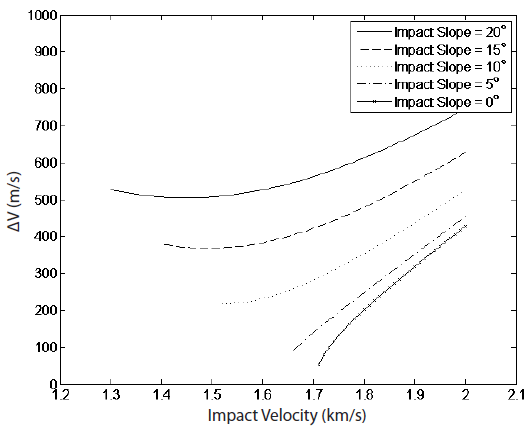
In the case of scenario 1, the initial orbit is a circular orbit with an altitude of 100 km. According to the simulation procedure designed in Section 3.1, the required ΔV, based on the impact slope and velocity, can be obtained. If the initial settings of the impact slope and velocity are different, a different ΔV value will be obtained, as shown in Fig. 4. As the impact slope is smaller, a smaller ΔV is required. Also, a larger impact velocity needs a larger ΔV. For each impact slope, the minimum ΔV and the impact velocity for that ΔV can be calculated, as in Table 1. A smaller impact slope requires a smaller ΔV but necessitates a larger impact velocity. A small ΔV is preferred with respect to cost reduction, but a large impact velocity should be avoided because it means a shorter measurement time. The initial orbital elements for entering impacting trajectories with the minimum ΔV and an impact slope of 10°, 15°, and 20° are shown in Table 2. They are in the lunar-centered fixed coordinate system, consisting of the equatorial plane and the axis of rotation of the Moon.

|
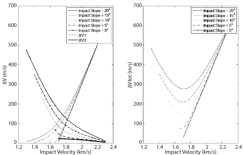
The same experiment is conducted for scenario 2. Two different ΔVs can be calculated as shown in Fig. 5. ΔV1 is defined for the first maneuver from the initial orbit to the transfer orbit, and ΔV2 is defined for the second maneuver from the transfer orbit to the final impact trajectory. The total ΔV is the sum of ΔV1 and ΔV2. As the impact velocity is varied from 1.3 km/s to 2.3 km/s by 0.01 km/s, the required ΔV is calculated. The ΔV1 increases as the impact velocity increases, and ΔV2 decreases as the velocity increases. In the same way, the experiment is repeated with different impact slopes, such as 20°, 15°, 10°, 5°, and 0°, and they are denoted by the different line styles. As such, the total ΔV has a minimum for each impact slope, shown in Table 3. A smaller impact slope requires less ΔV. The impact velocity for the minimum ΔV is about 1.70 km/s for all impact slope cases, which is different than scenario 1. In general, the minimum ΔV in scenario 2 is smaller than in scenario 1. In addition, the initial orbital elements for entering the transfer orbit with a minimum total ΔV for impact slopes of 10°, 15°, and 20° are shown in Table 4, expressed in the lunar-centered fixed coordinate system. As mentioned earlier, scenario 2 requires two maneuvers, unlike the other scenarios. The first maneuver can be performed separately from the lunar orbit, but the second maneuver must be conducted by the CubeSat itself. That is, the CubeSat must be loaded with fuel to produce a thrust equivalent to ΔV2 from Table 3. As a result, additional analysis for scenario 2 was not performed since loading fuel within a 3U-sized CubeSat for the purpose of orbit transition is considered impractical.

|
Scenario 3 is a case where the separation of the CubeSat is conducted during the lunar orbit insertion. The orbital elements are as follows for the three LOI stages (Choi et al. 2014). The orbit after the first LOI maneuver is a 12.0 hr periodic elliptical orbit with a 100 km periapsis altitude. The second LOI orbit is a 3.5 hr periodic elliptical orbit with a 100 km periapsis altitude. The last LOI orbit is a circular orbit with an altitude of 100 km. In the case of the last orbit, the initial orbit is the same as in scenario 1. Therefore, the simulation of scenario 3 is performed for the first and the second LOI orbits. Scenario 3 is different than scenarios 1 and 2, as the release point is fixed in the initial orbit.
In case of the scenario 3-1, the CubeSat is released at the apoapsis of the orbit with a semi-major axis of 6,142.577 km, an eccentricity of 0.700744528, and an inclination of 90°, as shown in Fig. 3. If the right ascension of ascending node (RAAN) is different, the impact velocity toward the swirl surface becomes different, as shown in Table 5. Similarly, as the argument of periapsis (AOP) is increased, the impact velocity increases. If the impact velocity is large, a larger ΔV is required. The minimum ΔV is shown in Table 6. A smaller impact slope requires a smaller ΔV, as well. The impact velocity for the minimum ΔV is about 2.2 km/s for all impact slope cases. The minimum ΔV in the scenario 3-1 is 147.0 m/s for the case of a 20° impact slope and is generally smaller than in scenarios 1 or The orbital elements where the CubeSat is separated from the orbiter are in Table 7. In the case of scenario 3-2, the CubeSat is released at the apoapsis of the orbit with a semi-major axis of 2,701.522 km, an eccentricity of 0.3195688, and an inclination of 90°, as shown in Fig. 3. The CubeSat maneuvers to fall from this initial orbit into a specific impact position with a 20° impact slope. Similar to scenario 3-1, the required ΔV differs according to the RAAN and the AOP, as shown in Table 8. The minimum ΔV is shown in Table 9. A smaller impact slope requires less ΔV, and the impact velocity for the minimum V is about 1.9 km/s for all impact slope cases, which is still too fast. The minimum ΔV is larger than that in scenario 3-1, but still smaller than those in scenarios 1 or 2. The separation orbital elements are in Table 10.

|

|
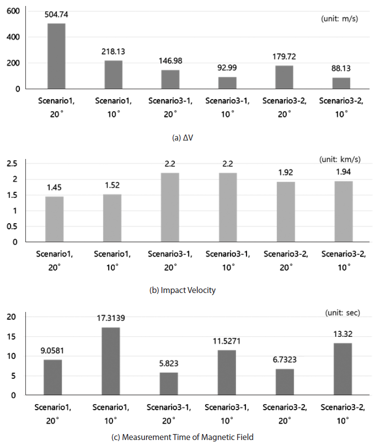
From the results of ΔV analysis in Section 3.2, three critical parameters— ΔV magnitude, impact velocity, and measurement time of magnetic field—are compared for all scenarios, as shown in Fig. 6. First, scenario 1, which required the largest ΔV, was the most expensive in terms of fuel. On the other hand, scenario 3-1, which required the smallest ΔV, was most favorable. On this point, the maximum ΔV of a CubeSat is limited to 410 m/s (Hruby et al. 2012). If that is considered to be the constraint, all scenarios except the case of scenario 1 with 20° impact slope can be selected. However, the impact velocity also needs to be compared. How fast the CubeSat passes above the Reiner Gamma swirl affects how long it can observe the magnetic data of the magnetic anomaly. Considering the impact velocity, the time it takes to measure the lunar magnetic field within 5 km of altitude can be calculated. In the case of scenario 1, the measurement time is 9.0581 sec when the impact slope is 20°. On the other hand, for scenario 3-1, it is 5.8230 sec with the same impact slope, which is shorter than that of scenario 1. In the case of scenario 3-2, the measurement time is 6.7323 sec. Remembering that the purpose of the CubeSat mission is to measure the magnetic field of the swirl region, it is evident that the measurement time is directly related to the success of the mission. The faster the CubeSat passes above the swirl, the less advantageous it is for the mission objectives. Therefore, scenario 1 is the most advantageous. As a result of the ΔV analysis, scenario 1 with an impact slope of 15° is selected as the best scenario since it satisfies the ΔV constraint and involves the longest measurement time.
4. ERROR PROPAGATION ANALYSIS
The initial error that occurs when the CubeSat performs maneuvers in an actual space environment results in an error in the final impact position of the CubeSat. So, in error propagation analysis, the ΔV error is randomly generated, and the sensitivity of the impact position error to the ΔV error is evaluated. There are three main causes of ΔV error. The initial errors at maneuvering are the ΔV error, the position/time error, and the velocity error of the CubeSat at the moment when the thruster gives a ΔV.
The first factor is the error in ΔV itself. When the CubeSat is separated from the orbiter, the catapult or the thrusters will generate ΔV. If ΔV has an error with an exact desired ΔV, the impacting trajectory and the final position on the surface may differ. The ΔV error can be a magnitude error, in-plane angle error, or out-of-plane angle error. It is assumed that the ΔV elements are Gaussian-distributed and have errors of 5 %, 5°, and 5°, respectively, for each component shown in Fig. 7. These are based on the error scales used in the maneuver planning and analysis of the Lunar Atmospheric and Dust Environment Explorer (LADEE) mission (Hawkins et al. 2015). 1,000 sets of ΔV with random errors are generated in MATLAB. First of all, the 1σ error for the magnitude error is 5 % of the desired ΔV magnitude. Then, the 1σ error for direction in the CubeSat’s orbital plane is 5°. Finally, the 1σ error for the direction perpendicular to the CubeSat’s orbital plane is 5°. With these 1,000 sets of ΔV, the simulations of the CubeSat’s impacting trajectory are conducted with GMAT. Here, it is necessary to locate the CubeSat at the specific desired position with the desired velocity. It is also necessary to maneuver the CubeSat at the specific desired moment.
The second factor is the error of the position at which the CubeSat performs ΔV. If the position of the CubeSat conducting the maneuver is different than expected, the desired impacting trajectory will not be reached. The error of maneuver position error is due to the orbit determination error of the CubeSat. Here, the orbit determination error is defined to include the time error (Policastri et al. 2015). As the reference orbit of scenario 1 is the circular orbit of 100 km altitude, an orbit determination error of 1 km is equal to a time error of 0.65 sec, because the CubeSat’s speed is about 1.6331 km/s in the reference orbit. CubeSat’s orbit determination error is estimated since the Korean lunar orbiter will have an accuracy of 1 km (1σ) orbit determination error. The position error can be in the radial direction, along-track direction, or cross-track direction, as shown as Fig. 8. After generating 1,000 sets of Gaussian-distributed random positions, each trajectory is propagated until it impacts the lunar surface.
The third factor is the maneuvering velocity error. If the CubeSat has a velocity error, it means that the CubeSat is on a different initial orbit. Therefore, if there is an error in velocity at the moment of maneuvering, it causes a final impact position error in the radial direction, along-track direction, or cross-track direction. The 1σ error is designed to be 0.001 km/s for the velocity error because this is 10-3 times the position error. The initial velocity error is presented in Fig. 9.
Finally, when the CubeSat conducts the maneuver, all initial errors, including the ΔV error, position error, and velocity error, are generated, and the final impact position error is analyzed. Similar to ΔV analysis, perturbation effects, such as the non-sphericity of the Moon’s gravity, third-body gravitational forces, and solar radiation pressure, are considered. Subsequently, it will be possible to examine if the CubeSat mission can be successful by reflecting all initial error and perturbation factors to the CubeSat’s mission orbit.
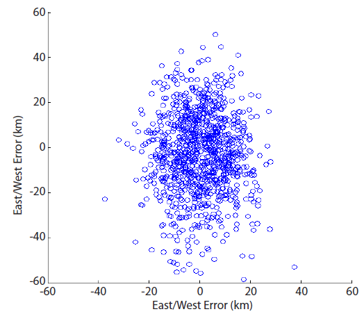
At first, an error in ΔV can depend on the accuracy of the equipment that separates the CubeSat from a mothership. The final impact position error when the ΔV magnitude and its direction in two axes occur simultaneously is shown in Fig. 10. In scenario 1 with an impact slope of 20°, the position error in the east-west direction and the north-south direction error are described in Table 11. The magnitude error of ΔV and the error of the in-plane direction influence the north-south position error in the final impact position. So, it is larger than the east-west position error, which is caused by the out-of-plane error of ΔV. The final impact position error averages 18.036 km with a standard deviation of 10.574 km due to the ΔV error.
The second error propagation analysis is due to the maneuver position error (i.e., orbit determination error) of the CubeSat. The final impact position error in the case where there are errors in the radial direction, the along-track direction, and the cross-track direction is shown in Fig. 11. In Table 12, the impact positon error of scenario 1 in the east-west direction and the position error in the north-south direction can be compared. The east-west error is caused because of the radial direction position error and the along-track position error, and the north-south error is due to the cross-track position error. The final impact position error caused by the orbit determination error is 2.369 km on average and the standard deviation is 1.512 km. It is less sensitive than the case where the error exists in ΔV itself.
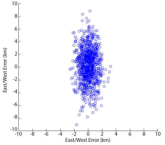
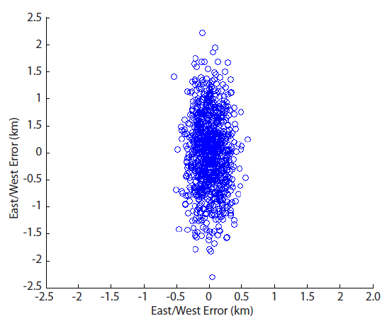
The third initial error is the velocity error at the CubeSat maneuver. If the initial velocity of the CubeSat is different from the initial orbit of scenario 1, which is circular, the reference orbit of the CubeSat ceases being a circular orbit, becoming an elliptical orbit. The velocity error is also composed of the radial component, the along-track component, and the cross-track component. With all of these errors, the final impact position error is shown in Fig. 12. The east-west error and the north-south error are presented in Table 13. As with the effects of the position errors, the final position error is larger for the north-south error than for the east-west error. The total impact position error caused by the initial velocity error is 0.5959 km and the standard deviation is 0.3902 km. This is less sensitive than the ΔV error or the position error.

|
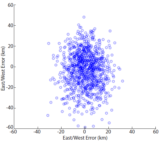
Synthetically, the effects of these three initial errors can be considered simultaneously. As we have seen in the results for each initial error, the error in the north-south direction of the CubeSat from the lunar equator is larger than that in the east-west direction. As a result, the total north-south error is about twice the east-west error. The total impact position error without perturbation effects is 18.270 km on average with a standard deviation of 10.476 km. As shown in Fig. 13, the worst impact position error reaches more than 50 km, which is much larger than the 36.72 km radius of the Reiner Gamma region. Perturbation effects, including the lunar non-spherical gravity, the Earth and the Sun’s gravitational forces, and the solar radiation pressure, should be considered for practical orbit propagation. With the perturbation effects, the question is how large the final impact position error can be, propagated from the initial errors. The average of the impact position error is 18.272 km, with a standard deviation of 10.478 km, as shown in Table 14. It is seen that the error difference is about 0.002 km. From this result, the perturbation effects are relatively insignificant compared to the initial errors’ effects.

|
The results in Table 11–14 involve the case of scenario 1 with an impact slope of 20°. The same analyses are also conducted for impact slopes of 15° and 10° for the other scenarios. With the perturbation effects, the results for each scenario are shown in Table 15. For all scenarios, the smaller the impact slope is, the larger the final impact position error tends to be. In the case of scenario 3-1, the 1σ impact position error seems to be smaller for an impact slope of 10° than for 20°. However, the probabilities of mission failure, when the CubeSat does not impact but remains in orbit around the Moon, are 24.9 % for an impact slope of 20° and 2.60 % for 10°, following the tendency. As mentioned earlier, the higher the altitude of the initial orbit at which the CubeSat begins to descend, the greater the final impact position error. This is because the higher the altitude, the longer the flight time is for the CubeSat to reach the swirl position, and finally, the more error is accumulated, including the perturbation effects.

|
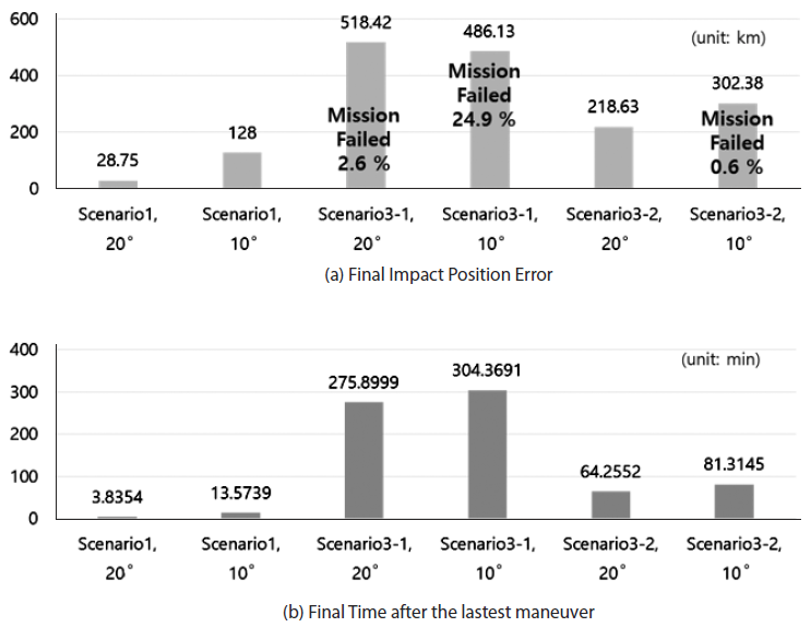
Except for scenario 1 with an impact slope of 20°, which is excluded by the ΔV constraint in Section 3.3, the final impact position errors for all cases exceed the radius of the Reiner Gamma swirl. This means that additional orbit control is needed for a successful mission operation. The final impact position error had larger values in scenarios 3-1 and 3-2 than in scenario 1. This is attributed to the fact that the height at which the CubeSat conducts the maneuver and starts to descend is much higher in scenario 3. If the altitude of the CubeSat separation is higher, the flight time will be longer, the initial errors will be propagated more, and the perturbation effects will accumulate for a longer time. The flight time of the CubeSat is 3.84 min in scenario 1 with an impact slope of 20°, which has the lowest separation height. On the other hand, the flight time is 275.90 min for scenario 3-1, and 64.26 min for scenario 3-2, as shown in Fig. 14. The lunar CubeSat must impact as precisely as possible above the Reiner Gamma region. Therefore, it is disadvantageous that separation occurs at a higher initial orbit.
5. CONCLUSIONS
In Sections 3.3 and 4.3, the parameters that are directly related to mission success were summarized by scenarios. Scenario 1 was the most advantageous in terms of the impact position error that can practically occur, the flight time in which perturbation effects will be of significance, and the impact velocity and measurement time necessary to achieve the mission’s scientific goal. Therefore, the current study concludes that scenario 1 with an impact slope of 15° is the scenario to be selected as the mission orbit. In this case, the impact position error is least among the scenarios where ΔV does not exceed the CubeSat separation constraint.
For the selected mission orbit, the required ΔV is 368.148 km/s. If there is no initial error in this ΔV at separation, then an accuracy of 4.2592 km for the position error and 0.000788 km/s for the velocity error are required for the CubeSat to fall within the Reiner Gamma swirl’s radius. However, since there are various initial errors in ΔV in the actual situation, it is necessary to achieve a more precise position and velocity determination error than those values. As in the error propagation analysis in Section 4.1, it is assumed that there are errors of 1 km in the maneuver position, 0.001 km/s in the maneuvering velocity, and 5 % and 5° in the ΔV magnitude and direction components, respectively. In this case, the final impact position is missed as the impact occurs 37.507 km from the center of the swirl. To achieve the mission objectives, impacting within the radius of the target region without additional orbit control, the required conditions are determined as follows. First, the position and velocity errors remain the same. Then, the required error accuracy of the ΔV magnitude and direction components is calculated. Among the 1,000 simulations propagated from the designed initial errors, the final position errors that are less than 32.76 km are extracted. The distributions of the ΔV magnitude and direction errors are presented in Table 16. If the ΔV magnitude error is about 3.8 % and the ΔV direction error is about 4.6°, the CubeSat will fall within the radius of the Reiner Gamma swirl, even though position and velocity errors initially exist.

|
